Cars contain more and more electronics and the systems are becoming increasingly complicated, which is why it has become essential to be able to access this information. The OBD2 port has therefore been adopted by car makers and is available in all vehicles.
The OBD standard (On Board Diagnostic) was implemented initially by the CARB (Californian Air Resources Board) to control polluting emissions from vehicles. The arrival of electronic computers to manage the engine and associated computers enabled vehicles to reduce their pollutants. The OBD states that a vehicle should permanently monitor the smooth operation of the engine throughout its life.
There are several OBD standards:
- OBD or OBDI standardises the connector so that it is identical on all vehicles. The communication protocol remains more or less specific depending on the make.
- OBDII arrived in the United States in 1996 to specify common protocols.
- EOBD for European OBD based on OBDII is specific to European vehicles.
EOBD was implemented in Europe at the same time as the EURO3 standard for pollutants from vehicles. It states that emission failures must be signalled by means of an indicator on the dashboard and that the codes corresponding to the detected failures must be recorded by the vehicle.
Looking for a car diagnostics tool ?
Standards and dates of application
As a result, since EURO3 and the European directive 98/69/EC, the standard is applicable depending on the vehicles from the following dates:

Some vehicles not covered by the directive may nevertheless be compatible. It depends on how much manufacturers are in advance of the new directive and their willingness to implement the standard.
PS: It should be noted that commercial and company vehicles are also affected by this directive, but their application dates are different (2006/2007).
The engine fault indicator (MIL)

Euro 3 and its directive announced the arrival of a new indicator on vehicle dashboards. The MIL for "Malfunction Indicator Lamp" is an icon representing an engine unit in orange/yellow (red is prohibited) specified by ISO 2575. Opposite are some examples on various vehicle models.
This indicator is used to signal a problem in the vehicle's pollution control system. Depending on the faults, there are several possible modes of operation:
- Permanently lit : a fault affecting pollutant emissions has been detected and confirmed by the computer. The vehicle can continue driving...
- Flashing : : a fault that may cause the destruction of some vehicle devices has been detected. In this case, it is strongly recommended to stop the vehicle at the earliest opportunity. Usually this mode also means the vehicle switches to failsafe mode (engine speed and power are limited).
- Intermittent : a fault has been detected but the system has not confirmed the presence of the fault. The indicator switches off by itself.
- Off : In this case, no fault linked to pollution is active. This does not necessarily mean that a fault is not present. Some of them have very little affect on the operation of the vehicle for example a malfunction in the glow plugs as described in our case study.
The diagnostic connector
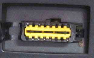
The directive states that the connector must be placed inside the passenger compartment. Usually it is located under the steering wheel in the fuse box or under the ashtray near the handbrake.
If you cannot find your diagnostic connector, go to our page location of OBD connectors to help you locate it.

Front view of the vehicle connector (here a Dacia Logan)
Connector pinout:

PS: It should be noted that the remaining pins may be used by the manufacturer as needed.
| Pin no. | Description |
|---|---|
| 1 | |
| 2 | J1850 BUS+ (SAE) |
| 3 | |
| 4 | Chassis ground |
| 5 | Signal ground |
| 6 | CAN High |
| 7 | K line (ISO) |
| 8 | |
| 9 | |
| 10 | J1850 BUS- (SAE) |
| 11 | |
| 12 | |
| 13 | |
| 14 | CAN Low |
| 15 | L line (ISO) |
| 16 | Battery + |
Description of the standard
While the port is standardised, several communication protocols remain possible depending on the manufacturers. They are represented below by the 5 columns ISO 9141-2, ISO 14230, SAE J1850, ISO 15765 and SAE J1979. It is the job of the software in the ELM interfaces to decode these various communication standards. Our software, converts the frames from the ELM interfaces into interpretable data based on the SAE J1979 standard.

The different protocols
Looking for a car diagnostics tool ?
The protocols based on lines K and L
The protocols described below all use the same medium (same electrical connection). However, differences in the data sent mean that they are not compatible with each other.
L'ISO9141-2
This protocol is used mainly by European manufacturers.
L'ISO14230 (KWP2000 or KW2000)
ISO14230 is the successor to ISO9141, and repeats the main characteristics. This protocol is used mainly by European manufacturers. Within this protocol, there are 2 "sub" protocols that differ mainly in their level of initialisation: slow init or 5 baud init and fast init.
Le KW1281, KW71 and KW82
These protocols (specified by SAE J2818) were mainly used by German car makers prior to the application of the EOBD standard.
Protocols based on SAE J1850
PWM (SAE J1850)
This protocol is mainly used by Ford. But it doesn't necessarily apply to FORDs sold in Europe that use the ISO protocol.
VPW (SAE J1850)
This protocol is mainly used by General Motors.
Protocols based on CAN
CAN (ISO 15765)
This is the protocol that will ultimately be used by all vehicles. It offers the best rapidity and flexibility.
CAN (SAE J1939)
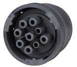
This protocol is mainly used for heavy duty vehicles (trucks, agricultural machinery, site machinery).

Most often, the diagnostic connector is not the same on this type of vehicle, and looks like the one above
OBD Modes
Whatever the protocol used, the OBD defines 10 modes of diagnostic. Not each mode is necessarily supported by the engine ECU (ECM). The more recent your vehicle, the greater the chance of it supporting more modes. The following page list of OBD2 compatible vehicles gives some examples of vehicles tested by users.
Mode 1
This mode returns the common values for some sensors such as:
- engine speed
- vehicle speed
- engine temperature (air, coolant)
- information about oxygen sensors and air/fuel mixture
Each sensor is characterised by a number called PID (Parameter Identifier) used to identify the parameter. For example, the standard stipulates that the engine speed has a PID of 12. The OBD standard (updated in 2007) includes 137 PIDs. As for the modes, not all cars support all PIDs. The page list of OBD2 compatible vehicles gives the PIDs supported in the various modes on certain vehicles.
Mode 2
This mode gives the freeze frame (or instantaneous) data of a fault. When a fault is detected by the ECM, it records the sensor data at a specific moment when the fault appears.
Mode 3
This mode shows the stored diagnostic trouble codes. These fault codes are standard for all makes of vehicle and are divided into 4 categories:
- P0xxx: for standard faults linked to the powertrain (engine and transmission)
- C0xxx: for standard faults on the chassis
- B0xxx: for standard faults on the body
- U0xxx: for standard faults on the communications network
More details and the definition of the generic fault codes are available on our page Standard OBD fault codes.
Mode 4
This mode is used to clear recorded fault codes and switch off the engine fault indicator.
Note : mostly it is not necessary to clear a fault that has not been diagnosed or repaired. The MIL will light again during the next driving cycle.
Mode 5
This mode gives the results of self-diagnostics done on the oxygen/lamda sensors. It mainly applies only to petrol vehicles.
For new ECUs using CAN, this mode is no longer used. Mode 6 replaces the functions that were available in Mode 5.
Mode 6
This mode gives the results of self-diagnostics done on systems not subject to constant surveillance.
Mode 7
This mode gives unconfirmed fault codes. It is very useful after a repair to check that the fault code does not reappear without having to do a long test run. The codes used are identical to those in mode 3.
Mode 8
This mode gives the results of self-diagnostics on other systems. It is hardly used in Europe.
Mode 9
This mode gives the information concerning the vehicle, such as:
- the VIN (vehicle identification number)
- calibration values
Mode 10 (or Mode A)
This mode gives the permanent fault codes. The codes used are identical to those in modes 3 and 7. Unlike modes 3 and 7, these codes cannot be cleared using mode 4. Only several road cycles with no appearance of the problem can clear the fault.